

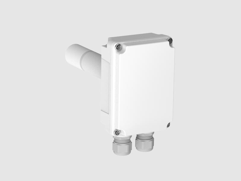
Transmissor de CO2 de duto GMD110
Para medições de alta precisão em aplicações HVAC
Nota de aplicação
As energy-efficiency regulations become stricter, so do the requirements for CO2 sensors. One of the forerunners in improving indoor air quality is the State of California. Its Building Standards Code sets performance criteria for CO2 sensors:
“CO2 sensors shall be certified by the manufacturer to be accurate within plus or minus 75 ppm at a 600 and 1000 ppm concentration when measured at sea level and 25°C, factory calibrated or calibrated at start-up, and certified by the manufacturer to require calibration no more frequently than once every 5 years.”
This indicates the importance of carefully examining specifications when choosing a sensor – not all sensors will perform in line with expectations.
Infrared sensors – also known as non-dispersive infrared (NDIR) sensors – dominate the HVAC CO2 sensor market for obvious reasons. They are highly sensitive, selective, and stable. They have a long lifetime and they are insensitive to environmental changes. Moreover, the traditional challenges with this technology – relatively high cost and difficulty in miniaturization – have been overcome.
Carbon dioxide has a characteristic absorbance band in the infrared region at a wavelength of 4.26 µm. When passing infrared radiation through a gas containing CO2, the CO2 molecules absorb part of the radiation.
The amount of radiation that passes through the gas depends on the concentration of CO2 present. An infrared sensor incorporating an infrared source, a detector, and an optical path quantifies the phenomenon (see Figure 1).
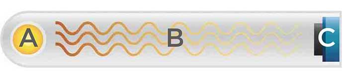
Figure 1. Infrared absorption of CO2 molecules can be detected with an infrared detector.
A: Infrared source. B: Optical path. C: Detector
After installation, HVAC CO2 sensors can typically operate with little or no maintenance for years, even for their entire lifetime. Selecting a sensor capable of reliable and accurate measurements in the long-term is therefore important. Although all infrared CO2 sensors share a common measurement principle, the technical solutions and measurement performance differ greatly.
A well-trained HVAC professional will be familiar with the differences between the various sensor types and their performance.
Single-beam single-wavelength sensors have a simple structure (Figure 2), comprising an infrared source, a measurement chamber, and a detector.
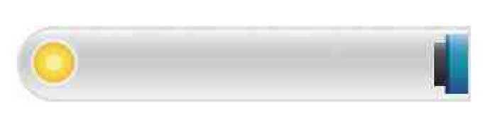
Figure 2. Single-beam single-wavelength sensor.
The challenge with this type of sensor is its substantial longterm drift. The intensity of the miniature incandescent light bulb – a typical infrared source in CO2 sensors – changes over time. In addition, dust and dirt may collect on the sensor surfaces. The sensor incorrectly interprets these changes as alterations in the CO2 concentration, resulting in unreliable measurements in the long run.
To compensate for this inherent instability, some manufacturers employ the automatic background calibration method. The sensor records the lowest CO2 reading within a given time period (typically several days) and readings are then rescaled assuming that the lowest recorded reading corresponds to fresh outside air (400 ppm of CO2). Unfortunately this is not always the case, as building occupancy patterns influence indoor CO2 levels. Facilities such as hospitals, retirement homes, residential buildings, and offices may have a round-the-clock occupancy, with lowest CO2 levels of around 600-800 ppm. Repetition of the faulty rescaling leads to erroneous CO2 readings, which in turn result in inadequate ventilation and lower indoor air quality. Moreover, in new buildings concrete carbonation can reduce the CO2 concentration to well below 400 ppm, so automatic background correction doesn’t work in that case either.
Dual-beam single-wavelength sensors (Figure 3) have a secondary infrared source to compensate for the infrared source drift. Curiously, manufacturers claim that as this secondary light source is seldom activated, it doesn’t suffer from aging. The sensor structure is unnecessarily complex, and the secondary infrared source adds an extra potential failure point. Moreover, dust and dirt rarely accumulate evenly around the sensor. To conclude, this sensor structure is relatively unreliable.
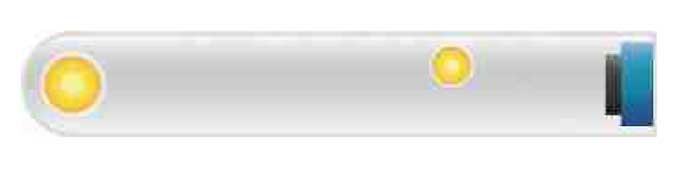
Figure 3. Dual-beam single-wavelength sensor structure.
Single-beam dual-wavelength sensors don’t suffer from the drift issues that affect the performance of single-beam single-wavelength and dual-beam single-wavelength sensors. This technology, which is commonly used in expensive filterwheel analyzers, measures not only at the absorption wavelength, but also at a reference wavelength where no absorption occurs.
Vaisala has packaged the single-beam dual-wavelength sensor into a compact structure that can be used in industrial transmitters. The reference is measured by placing an electrically tunable Fabry-Perot Interferometer (FPI) filter in front of the detector (Figure 4).

Figure 4. A single-beam dual-wavelength sensor with an FPI filter in front of the detector
The micromechanical FPI filter is electrically adjusted to switch between the CO2 measurement wavelength and the reference wavelength. The reference measurement compensates for any potential changes in the infrared source intensity, as well as for dirt accumulation in the optical path, eliminating the need for complicated compensation algorithms.
Simple and cost efficient, the single-beam dual-wavelength sensor is highly stable over time, requiring minimal maintenance.
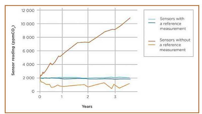
Figure 5 illustrates the difference in long-term stability between sensors that use a reference measurement (single-beam dual-wavelength sensors) and sensors that do not (single-beam single-wavelength sensors). The drift common in single-beam single-wavelength sensors originates from reduced infrared source intensity, resulting in too high CO2 level indication. However, sensor drift can also result in too low readings.
Figure 5. Long-term stability of Vaisala’s single-beam dual-wavelength sensors (Sensors with a reference measurement) versus single-beam single-wavelength sensors (Sensors without a reference measurement).
Most infrared CO2 sensors use a miniature incandescent light bulb as the infrared source (Figure 6), which are not the ideal source for sensors. Firstly, the initial light intensity varies greatly between units, making deployment challenging. Secondly, they suffer from inherent instability: tungsten evaporates from the thin filament and adheres to the glass surfaces, blackening the bulb walls.
As the filament becomes thinner, output intensity gradually degrades. The long-term stability of sensors without a reference measurement (single-beam single-wavelength and dual-beam single-wavelength sensors) suffers greatly (Figure 5). Other disadvantages include relatively high power consumption and limited lifetime.
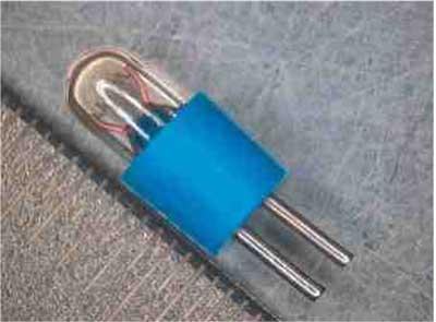
Figure 6. Miniature incandescent light bulb.
The next-generation infrared technology – microglow – solves many of the challenges that impact traditional infrared sources. The key advantages of microglow (Figure 7) are extended infrared source lifetime, reduced power consumption, uniform quality, and superior manufacturability at high volumes.
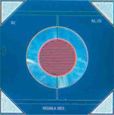
Figure 7. Vaisala-patented microglow, a silicon MEMS emitter infrared source.
Replacing the incandescent light bulb with microglow technology increases the sensor’s operational lifetime by 50%, while power consumption is only 25% that of traditional infrared sources.
The high amount of heat generated by incandescent light bulbs limits their applicability in multiparameter transmitters measuring not only CO2, but also humidity and temperature. As a temperature-dependent parameter, humidity can’t be measured reliably in the proximity of a heat source. The uniquely low power consumption of microglow enables high-quality humidity measurement in the same transmitter enclosure as CO2 measurement and also reduces the sensor warm-up time.
The intensity of microglow remains extremely stable throughout its lifetime (Figure 8). Other benefits include short response time and superior manufacturability, as the chip can be automatically assembled directly on the component board.
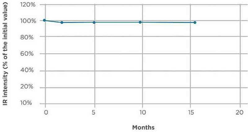
Figure 8. Microglow’s superior long-term stability.
Para medições de alta precisão em aplicações HVAC
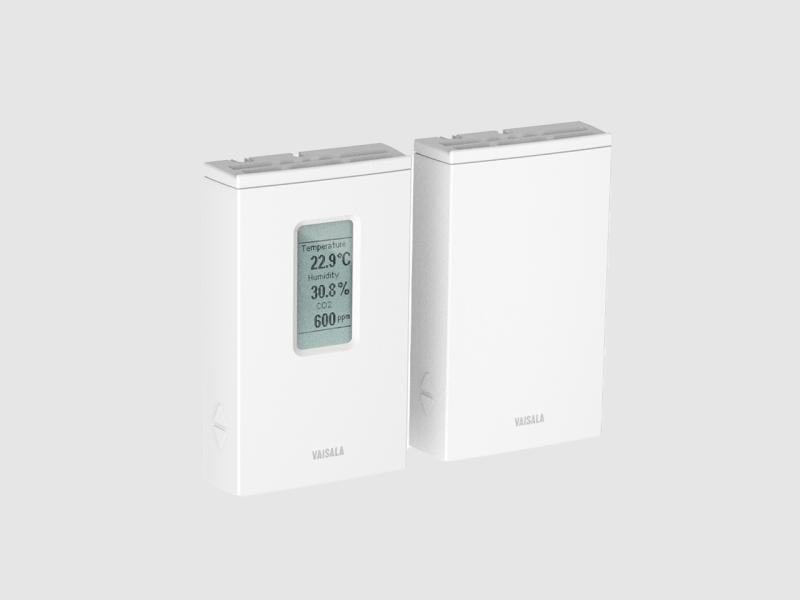
para projetos de construção verde
para projetos de construção verde
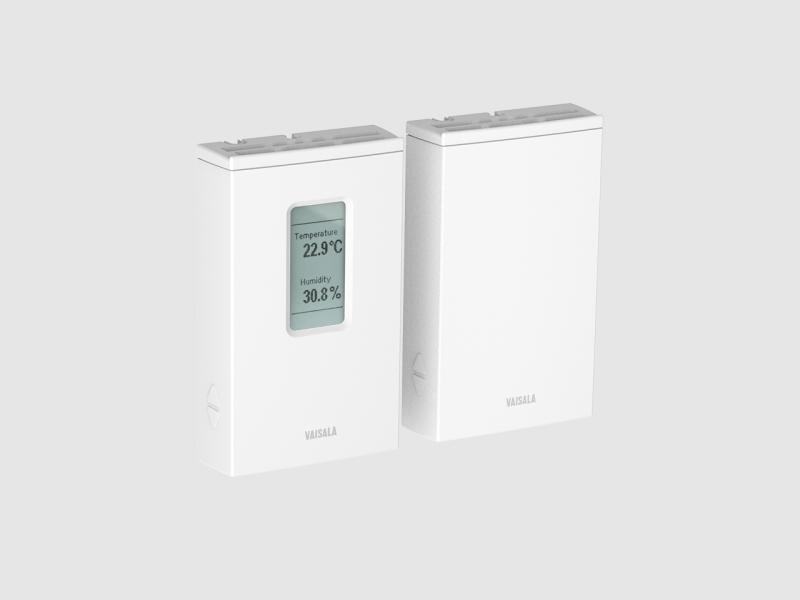
Transmissores de parede de ±1.7% de umidade relativa com um certificado para HVAC exigente
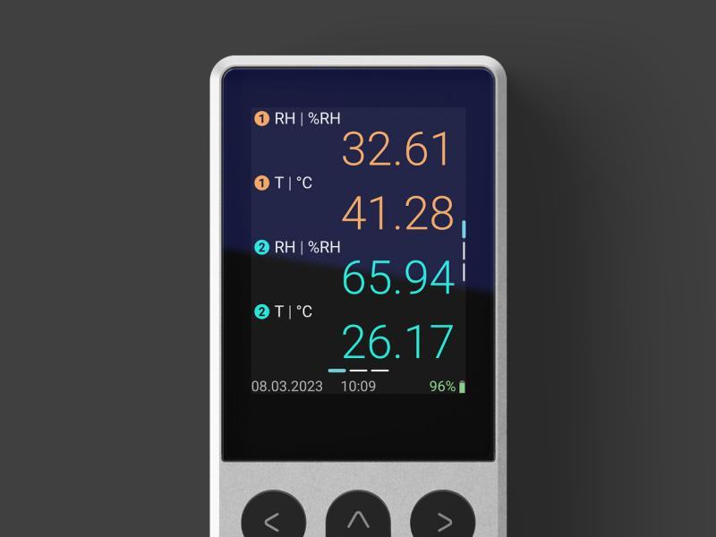
O mais novo integrante da linha Indigo de transmissores e sondas, o Indigo80 é um coletor de dados e indicador portátil e compacto. Ideal para…
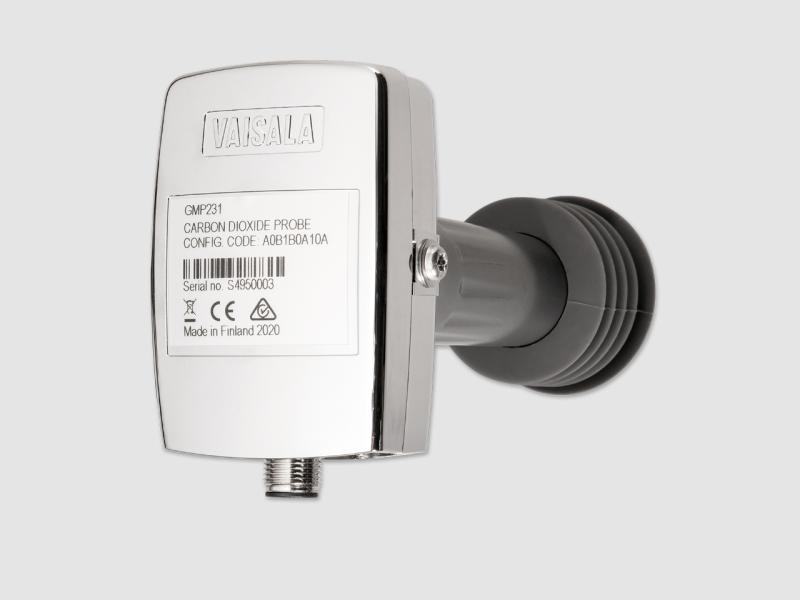
para incubadoras de CO₂

Princípio de funcionamento dos sensores infravermelhos, compensação por temperatura, pressão e umidade, e localização de transmissores.
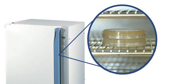
Por que o CO2 é crítico na cultura celular, o risco de condensação ao medir em alta umidade e temperatura, e por que a esterilização sem remover o…

Por que o O2 é reduzido e o CO2 é elevado em câmaras de atmosfera controlada, e quais instrumentos toleram o frio e a umidade elevada desse ambiente.

O que é a amostragem por equilíbrio, por que o aquecimento do sensor pode alterar a medição em campo, e qual faixa é necessária para perfis profundos…
Um especialista responde com a solução, o instrumento e o serviço adequados.
Instrumentos para cotar
Ainda não há instrumentos. É possível escrever mesmo assim: um especialista responde.