

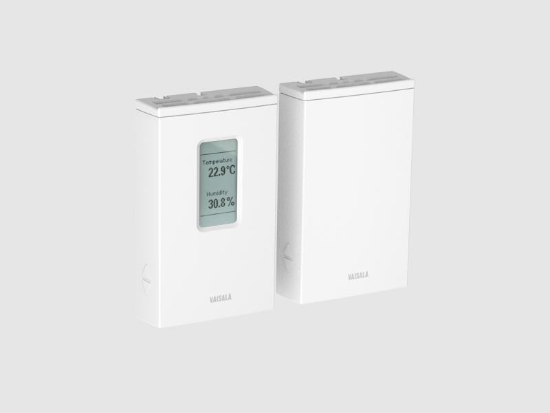
Humidity and Temperature Transmitter Series HMW90
±1.7%RH wall transmitters with a certificate for demanding HVAC
Technical note
This is the first of a series of three blog posts looking at common pitfalls when installing HVAC sensors, focusing on physical measurement errors that are caused by incorrect installation. This first post will concentrate on the installation of humidity, temperature, and CO2 wall sensors.
The most important thing to remember when installing wall sensors is that they are intended for measuring the conditions that humans are experiencing in a room. You should choose a representative location with free air flow and no heat sources nearby. Some of the most common errors include mounting the sensor in a place with very restricted air flow, like behind a cupboard, or in direct sunlight which may heat up the sensor, or close to some other heat source, like a radiator. It’s also worth noting that generic wall sensors are generally not designed to be mounted on the ceiling. If you want to mount your sensor on the ceiling you need to buy a special sensor that is designed for this purpose.
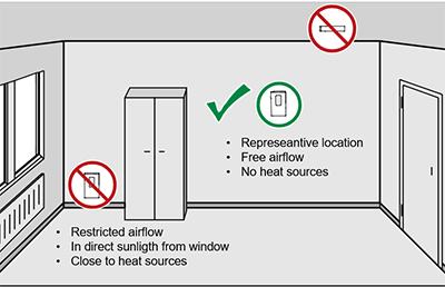
Figure 1: A representative mounting location of a HVAC wall sensor.
In a recent case a convention center thought their new control system, mounted in the rafters, was working very well, but when CO2 levels were checked at floor level, readings of about 2000 ppm were seen. The contractor explained that the sensors were installed in the rafters because it was more convenient to mount them up there. Although the CO2 level was at a perfectly acceptable level near the sensors, down at floor level, five or six meters below the rafters and where all the people were, the CO2 level was very high. Mounting the sensors in the rafters may have been practical, but it really wasn’t a good idea.
There are some very specific errors made when mounting wall sensors. Wall sensors are designed to be mounted in a certain direction, and if it says ‘this side up’, that’s what you should do. This is due to the fact that any electronics inside the wall unit will generate heat. If you mount a wall sensor in the correct orientation, the excess heat will be carried away by the air flow without disturbing the measurements. Unfortunately sensors are sometimes mounted sideways, in the belief that they look better that way. This is not a good idea: it will result in temperature measurements that are too high and humidity readings that are too low.
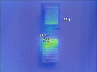
Figure 2. Thermal imaging shows considerable heat generation in wall sensors, especially in CO2 sensors and some other gas sensors.
As you can see in Figure 2, the heat can be quite easily detected by a thermal camera. This photo shows that the lower sensor is perfectly OK – it’s mounted in the correct direction. The issue here is that there’s a second sensor mounted above and the lower sensor is causing the bottom of the upper sensor box to heat up. If you have a carbon dioxide sensor, for example, it’s a very bad idea to mount a temperature or humidity sensor above it, so try to avoid doing this. Again, you will get temperature readings that are too high and humidity readings that are too low.
Another source of error could be pressure differences. If you have a room with underpressure, this might cause cold air or low-CO2 air to flow directly into the sensor and distort the results. The cable feedthrough is often the culprit here, so you might need to use a seal behind the sensor and especially the cable feedthrough – maybe some putty or something similar.
Pressure also affects CO2 readings. Carbon dioxide sensors often have barometric pressure compensation because they work by counting CO2 molecules. To measure the ppm accurately, the sensors need to know the correct ambient pressure. In practice, the sensors have either an active pressure sensor or a pressure setting. If you are using both outdoor and indoor CO2 sensors, it is important to make sure that they either all have active pressure measurements or, if you have a pressure setting, that it is the same in both the wall sensors and the outdoor sensor. If you don’t do this you will be introducing an offset into your system, which could increase or decrease your air flows.
Another source of error could be fresh concrete as concrete absorbs CO2. In rooms with exposed concrete surfaces CO2 levels will be quite low. If you mount a sensor directly on an exposed concrete surface, you will get an extremely low CO2 concentration inside the sensor box, which won’t be representative of the air outside. In some cases you can fix the situation by placing a plate behind the sensor that stops the flow of CO2. If you use a sensor with automatic background control (ABC) logic, it won’t work very well in locations that go down to about 200 ppm of CO2 without people around. Sometimes people assume levels will go down to about 400 ppm – which is the outside background concentration – and zero the sensor readings against that, but this isn’t a very good idea and won’t give reliable results.
It’s good to note a regular wall sensor is designed to work well in a normal office environment. If you have special conditions or an environment like a cleanroom where it is common to have forced downward air flow, these sensors might not work too well as the heat generated by the electronics will be carried down to the sensor, distorting the readings. In an application with downward air flow, you need to make sure that your sensor is designed for use in these conditions.
Wall sensor readings can also be distorted by a wall material that conducts heat, for example steel or concrete. If you bolt the sensor directly to the wall, it might not give a correct indication of the air temperature in the room – instead it’s indicating the approximate temperature of the wall itself. Most common wall materials found in offices won’t cause any difficulties, but if you have metal or concrete wall elements it’s a good idea to use some kind of insulation between the sensor and the wall material.
Stay tuned to our December post about the impact physical measurement errors have on HVAC duct sensor installations.
Learn more about our HVAC offering or contact us for more information..
±1.7%RH wall transmitters with a certificate for demanding HVAC
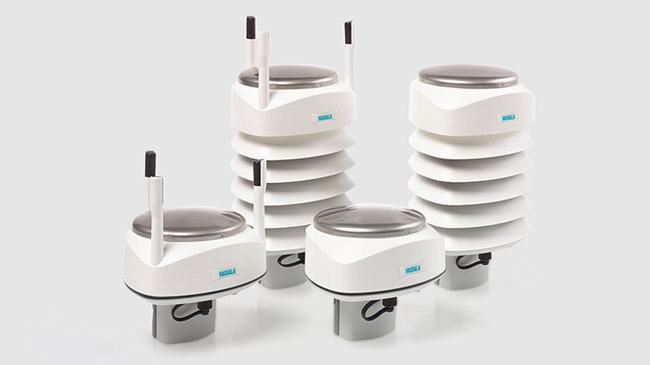
Vaisala Weather Transmitter WXT530 series is a unique collection of cost-effective sensors that accurately and reliably measure weather conditions…
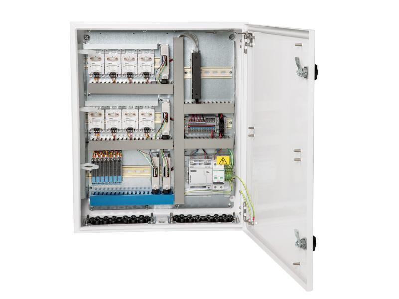
for cleanrooms and industrial settings
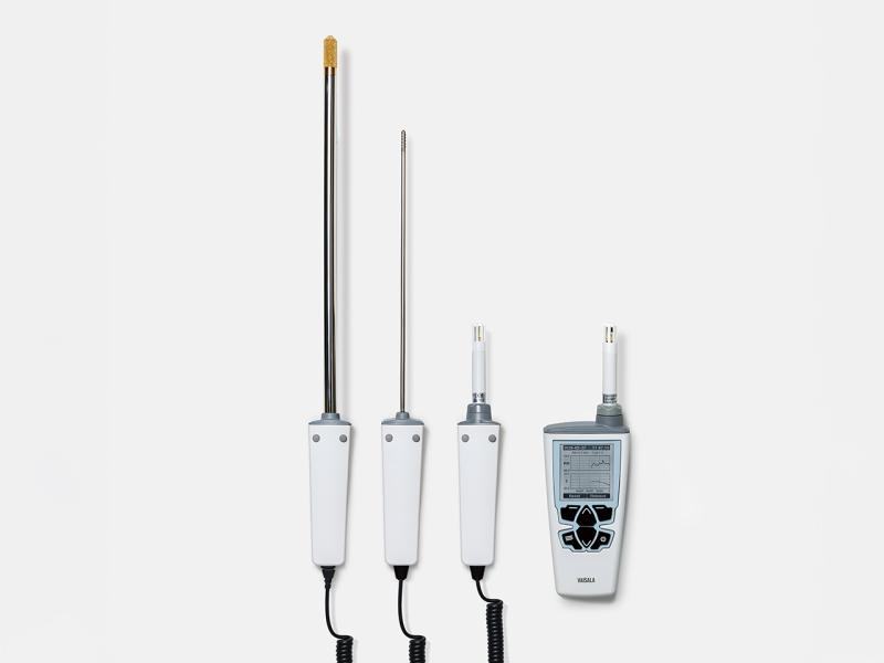
for quick inspections and spot-checking
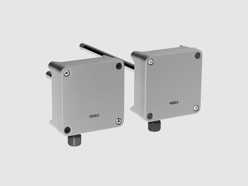
For high precision measurements in demanding HVAC applications
The Vaisala HUMICAP® Humidity and Temperature Probe HMP113 is a highly accurate and cost-effective humidity probe with a plastic enclosure. It has…
What relative humidity, dew point, absolute humidity and mixing ratio are, how temperature and pressure distort the reading, and why dew point is…
How humidity behaves in real conditions, the three most common measurement problems, and two practical scenarios —heated air and compressed air—…
When to measure relative humidity vs. dew point, what high and low humidity demand, how temperature and pressure factor in, and when a warmed probe…

Cooling accounts for up to 40% of a data center's energy demand. This Vaisala guide explains how measurement accuracy cuts costs and risks, with a…
A specialist replies with the solution, the instrument and the service that fit.
Instruments to quote
No instruments yet. An enquiry can be sent anyway: a specialist answers.