
How to Measure Carbon Dioxide (CO₂)
How infrared CO2 sensors work, how to compensate readings for temperature, pressure and humidity, and where to install transmitters for building, life science and industrial safety applications.
Carbon dioxide measurement is required across a wide range of applications — from building automation and greenhouses to life science and industrial safety.
This note summarizes the physical principles behind infrared CO2 measurement, how to compensate readings for temperature, pressure and humidity, where to place transmitters depending on the use case, and the risks associated with CO2 exposure.
This note covers
- Operating principle of infrared CO2 sensors
- The ideal gas law and how to compensate measurement for environmental factors
- Optimal locations for CO2 transmitters
- The effect of humidity on CO2 readings
- Safety risks associated with CO2
Operating Principle of Infrared Sensors
Carbon dioxide and other gases made up of two or more dissimilar atoms absorb infrared (IR) radiation in a characteristic, unique way. This makes them detectable using optical techniques. Water vapor, methane, carbon dioxide, and carbon monoxide are examples of gases that can be measured with an IR sensor, each with its own absorption band.
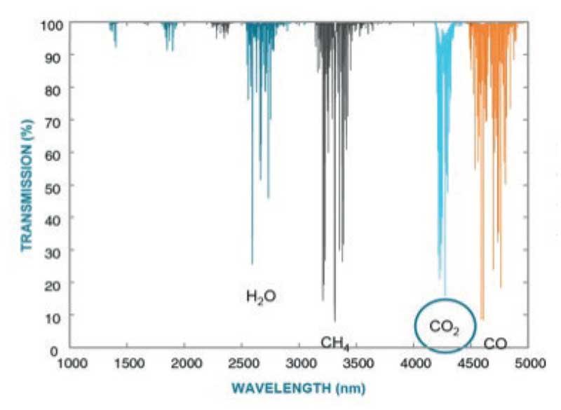
Infrared sensing is the most widely used technology for CO2 detection, with clear advantages over chemical sensors: it is stable, highly selective to the measured gas, has a long lifetime, and since the measured gas doesn't interact directly with the sensor, IR sensors withstand high humidity, dust, dirt, and other harsh conditions.
The key components of an IR CO2 detector are the light source, measurement chamber, an interference filter, and the IR detector. Infrared radiation travels through the measured gas toward the detector; a filter placed in front of the detector blocks wavelengths other than the one specific to the gas of interest. The detected light intensity is converted into a gas concentration value.
Vaisala's CARBOCAP® sensor applies this technology to measure the volumetric concentration of CO2, using an electrically tunable Fabry-Perot Interferometer (FPI) filter for dual-wavelength measurement: in addition to measuring CO2 absorption, the sensor performs a reference measurement that compensates for changes in light source intensity as well as dirt accumulation and contamination, keeping the sensor stable over time. AKRIBIS is an authorized Vaisala partner for distribution and technical support in the region — explore the full Vaisala instrumentation line.
The Ideal Gas Law
The ideal gas law is useful for estimating the effect of temperature and pressure changes on CO2 measurement, and it allows readings to be compensated accordingly.
An ideal gas is a hypothetical gas consisting of randomly moving identical point particles, negligible in size and with negligible intermolecular forces. In practice, real gases don't behave exactly this way, but the approximation reasonably describes their behavior.
The law relates the state of a given amount of gas to its pressure, volume, and temperature:
pV = nRT
- p = pressure [Pa]
- V = volume of the gas [m³]
- n = amount of gas [mol]
- R = universal gas constant (= 8.3145 J/mol·K)
- T = temperature [K]
Most gas sensors output a signal proportional to molecular density (molecules per volume of gas), even though the reading is expressed in parts per million (volume/volume). As pressure and/or temperature change, the molecular density of the gas changes according to the ideal gas law — and that effect is reflected directly in the sensor's ppm reading.
Typical CO2 instruments do not measure pressure and therefore cannot automatically compensate for its variations. When calibrated at the factory, instruments are usually set to sea-level pressure conditions (1013 hPa). When measuring at altitudes other than sea level, it's recommended to compensate for the pressure effect — either by entering the correct setting for internal compensation (constant pressure conditions) or by programming the compensation into an automation system or PC (changing pressure conditions). The same logic applies to the temperature effect, although more and more CO2 meters now measure and compensate for temperature internally, without requiring external compensation.
Table 1 shows, as a reference, how a CO2 sensor's reading (gas containing 1,000 ppm of CO2 at standard conditions) changes with temperature and pressure, according to the ideal gas law.
| Pressure (hPa) | Temperature (°C) | |||||||||
|---|---|---|---|---|---|---|---|---|---|---|
| -20 | -10 | 0 | 10 | 20 | 25 | 30 | 40 | 50 | 60 | |
| 700 | 814 | 783 | 754 | 728 | 703 | 691 | 680 | 658 | 638 | 618 |
| 800 | 930 | 895 | 862 | 832 | 803 | 790 | 777 | 752 | 729 | 707 |
| 900 | 1046 | 1007 | 970 | 936 | 904 | 888 | 874 | 846 | 820 | 795 |
| 1000 | 1163 | 1119 | 1078 | 1039 | 1004 | 987 | 971 | 940 | 911 | 883 |
| 1013 | 1178 | 1133 | 1092 | 1053 | 1017 | 1000 | 983 | 952 | 923 | 895 |
| 1100 | 1279 | 1230 | 1185 | 1143 | 1104 | 1086 | 1068 | 1034 | 1002 | 972 |
| 1200 | 1395 | 1342 | 1293 | 1247 | 1205 | 1185 | 1165 | 1128 | 1093 | 1060 |
| 1300 | 1512 | 1454 | 1401 | 1351 | 1305 | 1283 | 1262 | 1222 | 1184 | 1148 |
Optimal Locations for CO2 Transmitters
Avoid locations where people may breathe directly onto the sensor. Also avoid placing sensors close to intake or exhaust ducts, or near windows and doorways.
In demand-controlled ventilation, wall-mounted sensors provide more accurate data on ventilation effectiveness than duct-mounted sensors. Duct-mounted sensors are best suited to single-zone systems and should be installed as close to the occupied space as possible, with easy access for maintenance.
When measuring CO2 for personnel safety purposes, transmitters should be installed close to potential leakage points to enable early detection. The geometry, ventilation, and airflow of the monitored area need to be taken into account — the number and location of CO2 transmitters should be based on a risk assessment.
The Effect of Humidity on Measurement
The molecules of a gas mixture occupy the same system volume at the same temperature. According to Dalton's Law of Partial Pressure, the total pressure of a gas mixture is the sum of the partial pressures of all the component gases.
This is relevant to understanding the influence of water vapor on a CO2 sensor's reading. When water vapor is added to a dry gas at constant pressure, temperature, and volume, water replaces some of the gas molecules in the mixture. Similarly, when a gas sample is drawn from a high-humidity environment and allowed to dry before entering the measurement chamber of a CO2 meter, the loss of water molecules changes the gas composition and affects the measurement.
This dilution effect can be estimated using Table 2. Knowing the CO2 concentration of the already-dried gas, it's possible to calculate the CO2 concentration of the original high-humidity environment — this requires knowing the dew point (Td at 1013 hPa) or water concentration (ppm) of both the wet and dry conditions.
Example: a gas sample is drawn from an environment with a dew point of 40°C (73,000 ppm of water) into an environment of 20°C Td (23,200 ppm of water). The measured CO2 concentration of 5.263% at 20°C Td translates to 5.00% in the 40°C Td environment (5.263% × 0.950 = 5.00%). The lower reading is caused by dilution resulting from the higher water content at 40°C Td.
| Dried gas — Dew point (°C) / Water concentration (ppm) | Wet environment — Dew point (°C) / Water concentration (ppm) | |||||||||||
|---|---|---|---|---|---|---|---|---|---|---|---|---|
| -40°C 127 | -30°C 377 | -20°C 1 020 | -10°C 2 580 | 0°C 6 060 | 10°C 12 200 | 20°C 23 200 | 30°C 42 000 | 40°C 73 000 | 50°C 122 000 | 60°C 197 000 | ||
| -60°C | 11 | 0.9999 | 0.9996 | 0.999 | 0.997 | 0.994 | 0.988 | 0.977 | 0.958 | 0.927 | 0.878 | 0.803 |
| -50°C | 39 | 0.9999 | 0.9997 | 0.999 | 0.997 | 0.994 | 0.988 | 0.977 | 0.958 | 0.927 | 0.878 | 0.803 |
| -40°C | 127 | 1.0000 | 0.9997 | 0.999 | 0.998 | 0.994 | 0.988 | 0.977 | 0.958 | 0.927 | 0.878 | 0.803 |
| -30°C | 377 | 1.0000 | 0.999 | 0.998 | 0.994 | 0.988 | 0.977 | 0.958 | 0.927 | 0.878 | 0.803 | |
| -20°C | 1 020 | 1.000 | 0.998 | 0.995 | 0.989 | 0.978 | 0.959 | 0.928 | 0.879 | 0.804 | ||
| -10°C | 2 580 | 1.000 | 0.997 | 0.990 | 0.979 | 0.961 | 0.930 | 0.880 | 0.805 | |||
| 0°C | 6 050 | 1.000 | 0.994 | 0.983 | 0.964 | 0.933 | 0.884 | 0.809 | ||||
| 10°C | 12 200 | 1.000 | 0.989 | 0.970 | 0.939 | 0.890 | 0.815 | |||||
| 20°C | 23 200 | 1.000 | 0.981 | 0.950 | 0.901 | 0.826 | ||||||
| 30°C | 42 000 | 1.000 | 0.969 | 0.920 | 0.845 | |||||||
| 40°C | 73 000 | 1.000 | 0.951 | 0.876 | ||||||||
| 50°C | 122 000 | 1.000 | 0.925 | |||||||||
| 60°C | 197 000 | 1.000 | ||||||||||
Carbon Dioxide and Safety
| Concentration | Effect |
|---|---|
| 350 – 450 ppm | Typical atmospheric concentration |
| 600 – 800 ppm | Acceptable indoor air quality |
| 1,000 ppm | Tolerable indoor air quality |
| 5,000 ppm | Average exposure limit over 8-hour period |
| 6,000 – 30,000 ppm | Concern, short exposure only |
| 3 – 8% | Increased respiration rate, headache |
| > 10% | Nausea, vomiting, unconsciousness |
| > 20% | Rapid unconsciousness, death |
Carbon dioxide is a non-toxic, non-flammable gas. However, exposure to elevated concentrations can pose a risk to life. Whenever CO2 gas or dry ice is used, produced, shipped, or stored, CO2 concentration can rise to dangerously high levels. Because CO2 is odorless and colorless, leaks are impossible to detect by sight alone — which is why proper sensors are essential to protect personnel safety.
This technical content is based on Vaisala's research on infrared CO2 sensors. AKRIBIS is an authorized Vaisala partner for distribution and technical support in Latin America — explore the full Vaisala instrumentation line.
Instruments to measure CO2
-
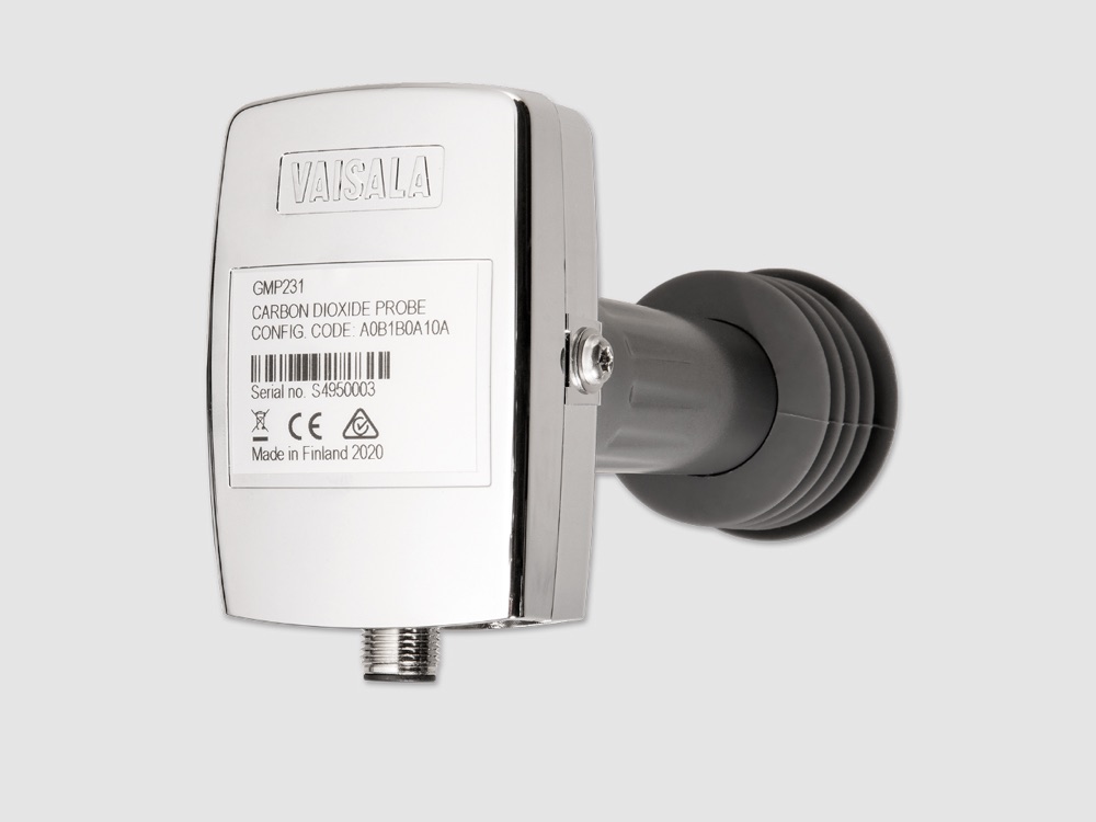 GMP231 Heat-sterilizable CO2 probe for incubators
 -
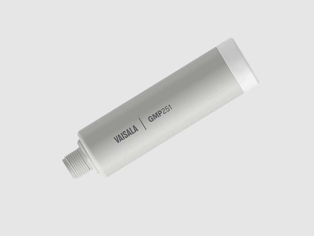 GMP251 CO2 probe for percentage-level measurements
 -
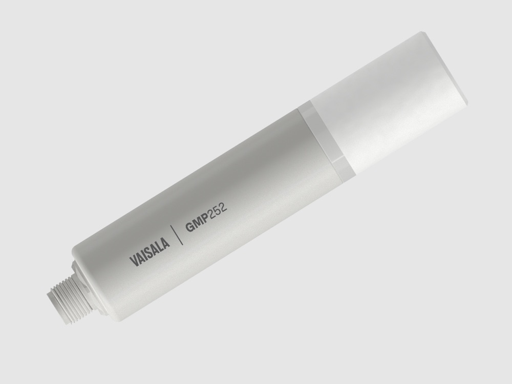 GMP252 CARBOCAP® CO2 probe for ppm-level measurements
 -
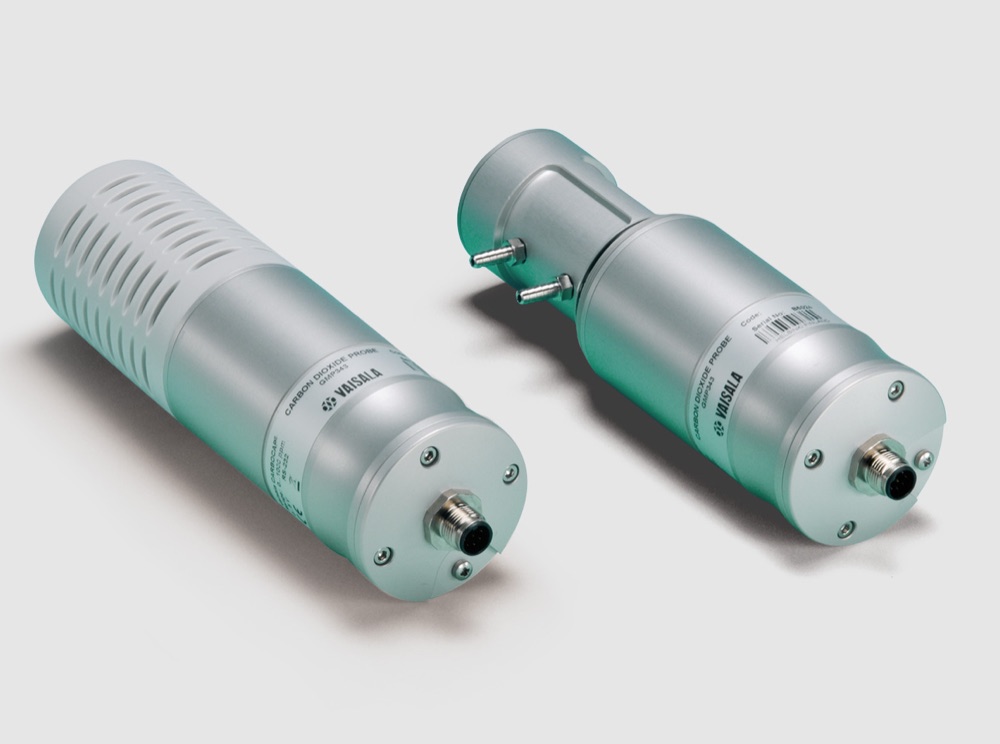 GMP343 Rugged CO2 probe for ecological measurements
 -
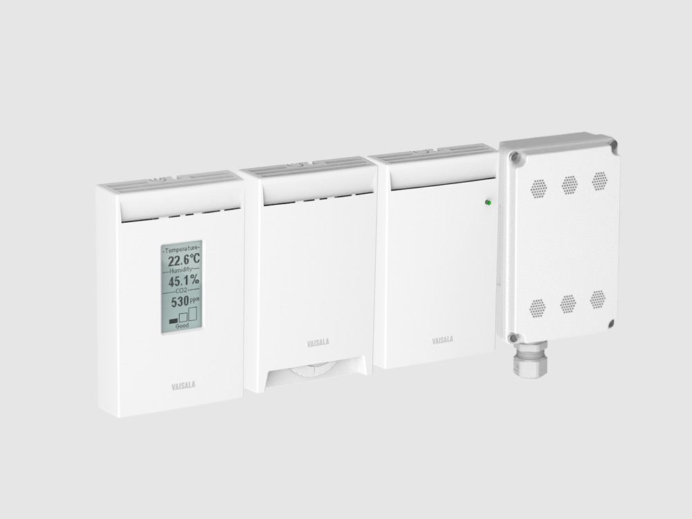 GMW80 Wall-mounted CO2, humidity and temperature transmitter for indoor air quality
 -
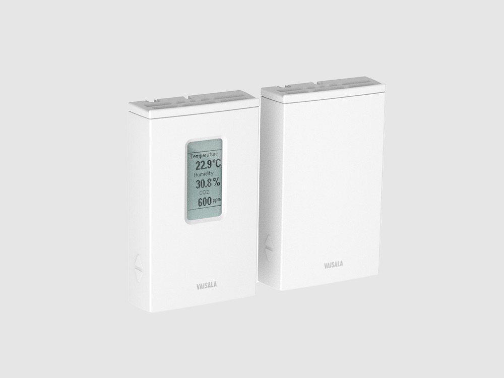 GMW90 Wall-mounted CO2 transmitter for green building projects
 -
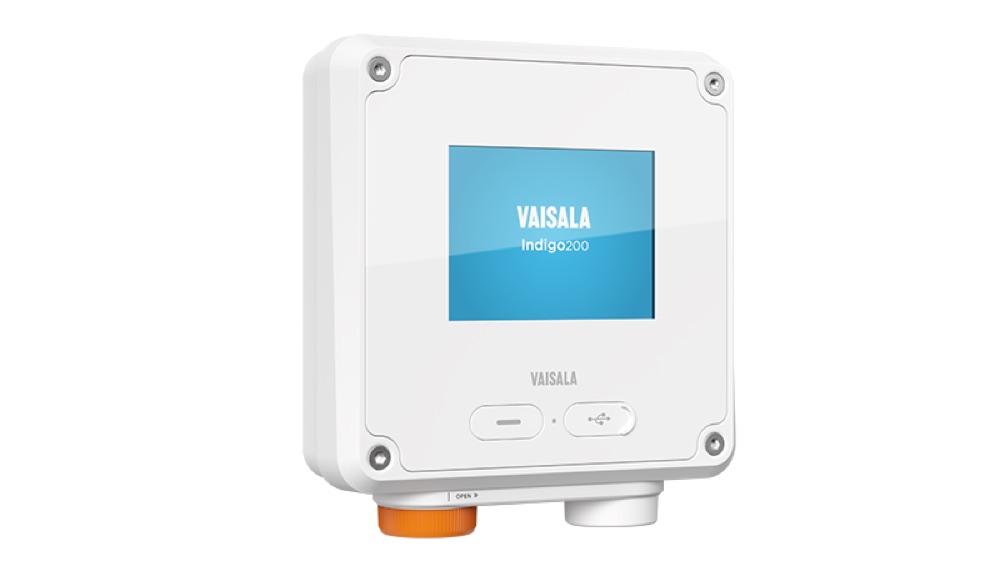 Indigo200 Compact single-probe transmitter for the Indigo ecosystem
 -
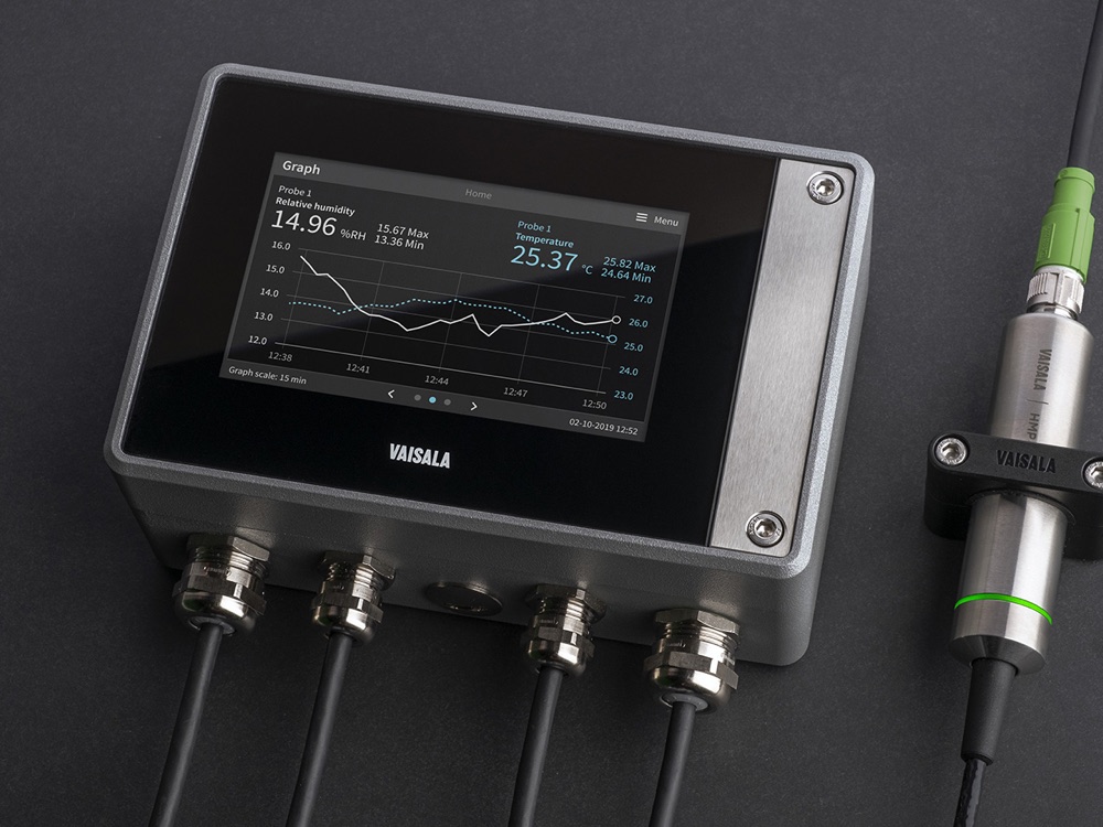 Indigo500 Universal transmitter for Indigo-compatible probes
 -
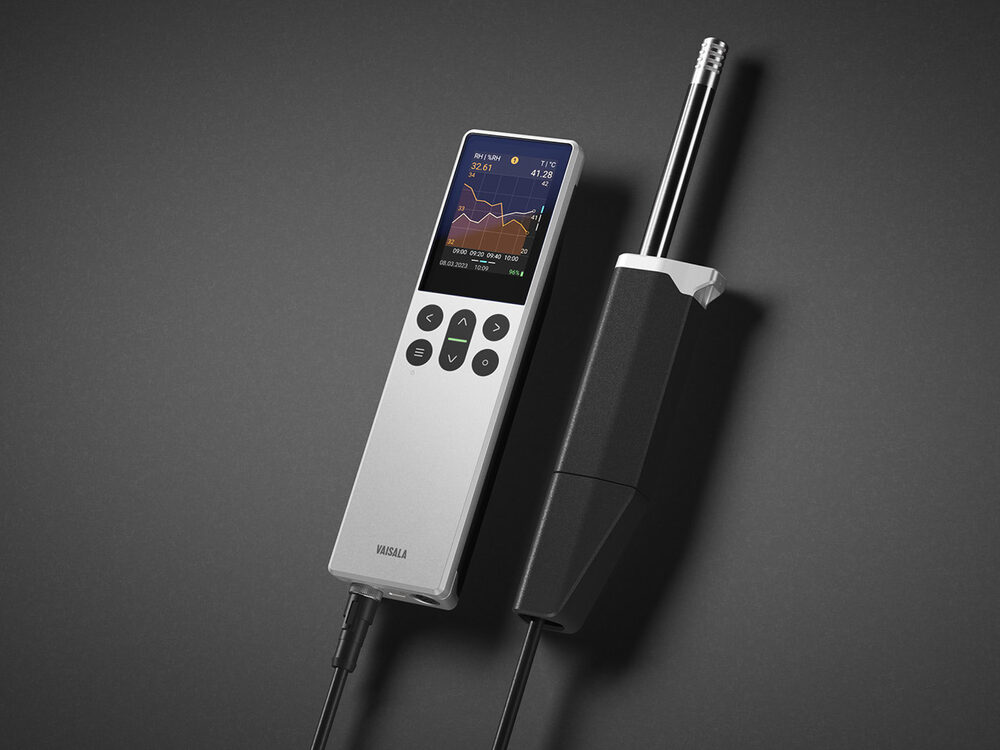 Indigo80 Handheld indicator for Indigo-compatible probes
 -
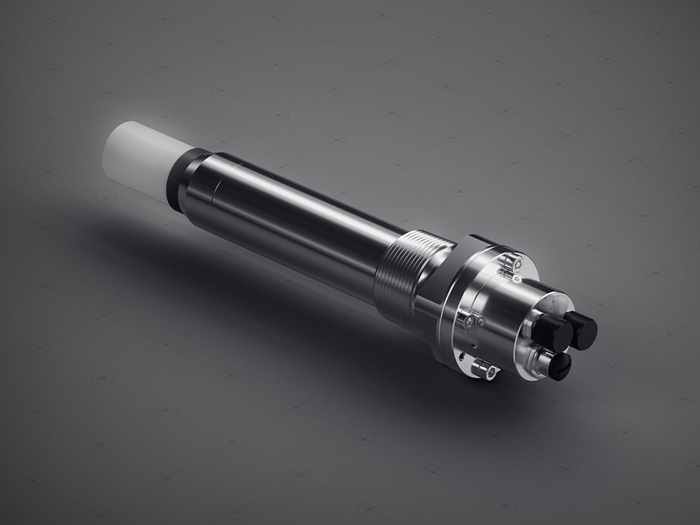 MGP241 Multigas CO2 instrument for carbon capture and storage
 -
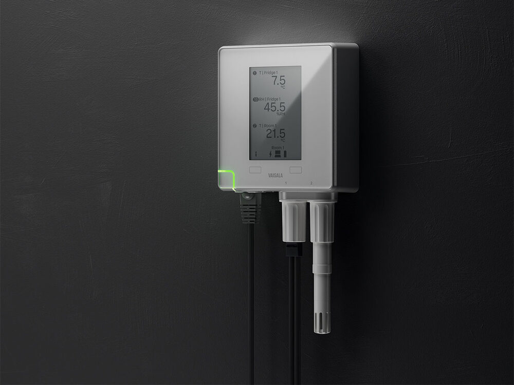 VDL200 Multi-parameter PoE data logger for continuous monitoring
¿Querés profundizar sobre este tema?
Nuestros especialistas pueden asesorarte en detalle sobre su aplicación en tu proceso.