

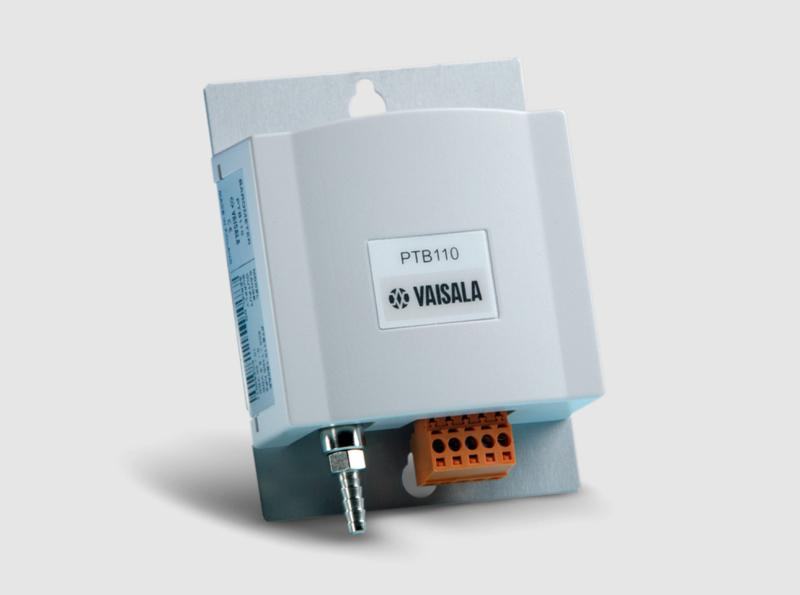
PTB110 Barometer
for industrial use
Technical note
Installing any electrical device in a hazardous location with an explosion risk requires special precautions and procedures – and installing an in situ measurement device into a gas pipeline presents its own specific risks and requirements. This blog post examines the practicalities of in situ installation into a boundary zone 0/1 hazardous area in a biogas plant.
Other risks worth bearing in mind are the presence of hydrogen sulfide, which is poisonous even at low concentrations, and the absence of oxygen, which may present a suffocation risk in confined spaces. Wearing a personal gas alarm that monitors methane, hydrogen sulfide, and oxygen levels is a must when installing instruments in this type of environment. It is also important to plan ahead and prepare a risk assessment document before commencing work.
The Vaisala MGP261 biogas measurement instrument is equipped with a 1½” NPT thread with a probe diameter of 40 mm and an insertion depth of 209 mm. It can be inserted through 1½” and 40 mm nominal-size ball valves, provided that the valve is a full-bore design and the joint between the valve and the main pipeline is not narrower than 40 mm. The only way to confirm this is to open up the valve to check the dimensions. Larger valves such as 2” or 50 mm can be used with a thread adapter to 1½” NPT, and they are often a good choice as the probe will fit through more easily.
Process connections are not always clearly marked, and the exact thread type may be hard to identify. In such cases it is best to use calipers to measure the diameter and possible taper of the thread, and a thread pitch gauge to determine the thread type. The MGP261 is shipped with a plastic 1½” NPT plug, which can be used as a thread identification aid.
If a ball valve is not available or wanted, for example because of cost considerations, a simple threaded socket welded to the pipeline is an effective solution. A short 50 mm pipe is used to adjust the position of the biogas probe so that its tip is between one third and two thirds of the pipe diameter. In addition to the main probe sampling port, a pressure transmitter process connection is needed, typically in the ¼ to ½” range depending on the pressure transmitter used.
In an NPT thread interface some of the male thread can remain visible after the connection is tightened. For further guidance on the correct installation of NPT-threaded equipment, see this blog post by Swagelok.
The smaller entry is primarily meant for 4-20 mA input from an Ex i (intrinsically safe) pressure transmitter and it leads to the intrinsically safe side of the connector box, which is isolated with a partition wall. Because the MGP261 contains an Ex i isolation transformer it is possible to directly connect an Ex i device to the probe. The two larger cable entries lead to the other side of the partition wall, where 4-20 mA analog output signals for methane, carbon dioxide, and water vapor are available in Ex e (enhanced safety) terminals together with RS485 (MODBUS/RTU) and 24 VDC power terminals.
Choose cable glands with Ex-approval, including strain relief and impact protection, and the correct cable diameter for the cables you are using. Some Ex-approved cable glands have an X in the approval code, meaning they are limited regarding strain relief and/or impact protection. If you are using this sort of cable gland, the cable must be secured to a cable tray or similar structure on the outside of the cable gland and appropriate impact protection must be built.
Particular attention should be paid to protective earth and signal ground connections, and cable shields should be terminated on potential equalization rails as shown in the MGP261 installation and safety guide. Measure the resistance between the potential equalization rail and the grounding screw on the MGP261 chassis; resistance must be less than 1 Ohm and the test must be documented as part of the installation report. This is particularly important as the MGP261 contains an Ex i barrier for the intrinsically safe pressure gauge as shown by the code [ia] in the Ex marking, and the protection of an intrinsically safe device relies on high-quality potential equalization.
We recommend using an experienced instrument integrator when installing instruments in biogas processes.
Visit the product page to learn more about Vaisala's 3-in-1 Methane, Carbon Dioxide and Humidity Multigas Probe MGP261 for Smart Control of Biogas Quality.
for industrial use
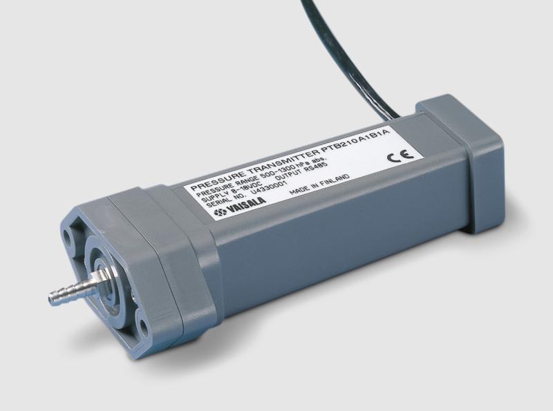
for harsh environments
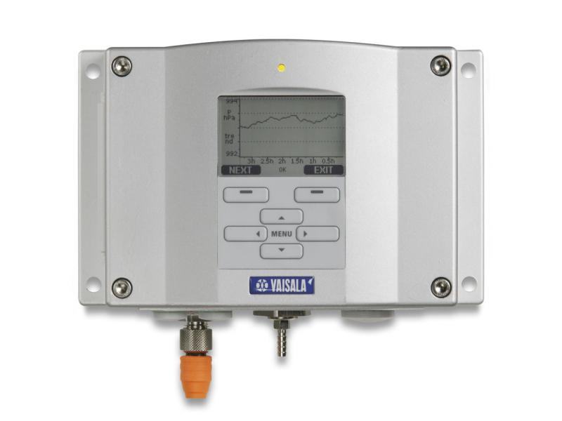
The Vaisala Digital Barometer PTB330 is designed to capture accurate barometric pressure readings under the harshest of conditions.
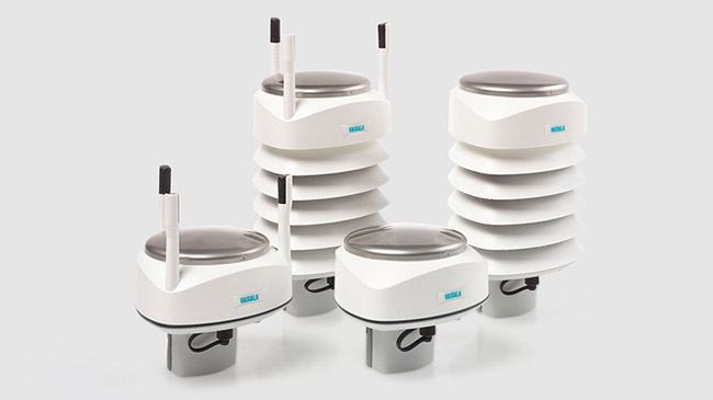
Vaisala Weather Transmitter WXT530 series is a unique collection of cost-effective sensors that accurately and reliably measure weather conditions…
Vaisala Weather Transmitter WXT530 series is a unique collection of cost-effective sensors that accurately and reliably measure weather conditions…
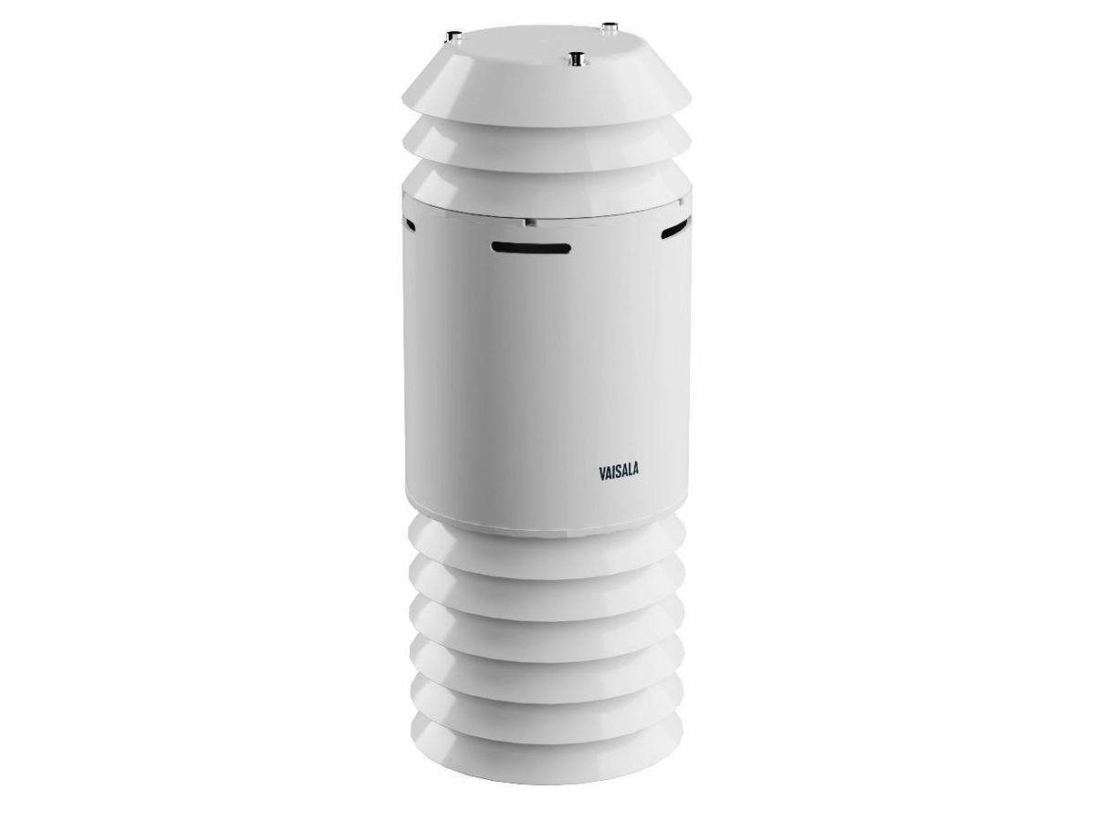
Vaisala Air Quality Transmitter AQT560 measures particles (PM10, PM2.5 and PM1) and the gases NO2, NO, O3 and CO in one compact, plug-and-play…
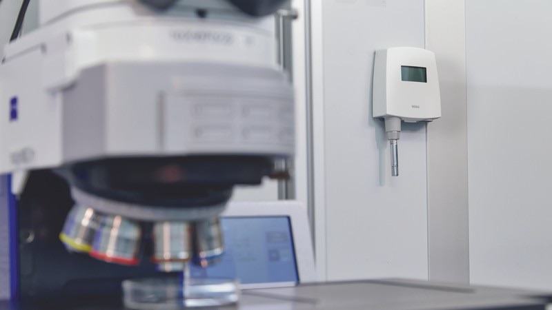
What relative humidity, dew point, absolute humidity and mixing ratio are, how temperature and pressure distort the reading, and why dew point is…
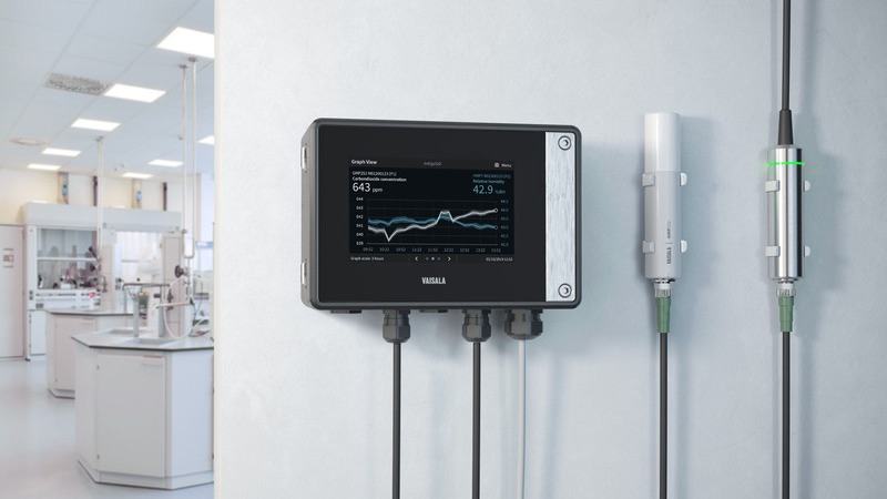
How humidity behaves in real conditions, the three most common measurement problems, and two practical scenarios —heated air and compressed air—…
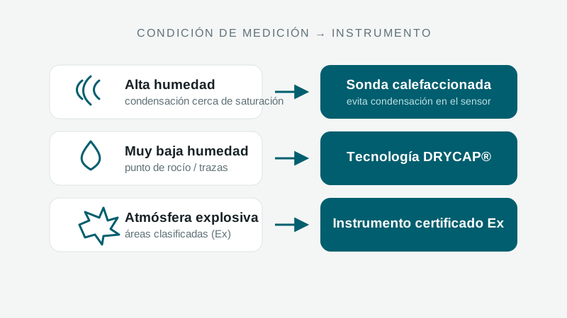
When to measure relative humidity vs. dew point, what high and low humidity demand, how temperature and pressure factor in, and when a warmed probe…

Cooling accounts for up to 40% of a data center's energy demand. This Vaisala guide explains how measurement accuracy cuts costs and risks, with a…
A specialist replies with the solution, the instrument and the service that fit.
Instruments to quote
No instruments yet. An enquiry can be sent anyway: a specialist answers.